Drafting Techniques
The 3D printer
Most 3D printer builds are based on a gantry design. A horizontal bridge or gantry holds the printer head which is a basically very similar to a hot melt glue gun. The printer head can slide back and forth along the bridge just like the hook on a gantry crane. The head is driven by timing belts and a stepper motor.
A 3D printer borrows the gantry principle from several other machines. CNC Gantry routers are commonly used in the woodworking industry. Instead of a hot melt glue head, the CNC gantry router uses a powerful wood cutting router.
There are also enormous CNC milling machines which use the gantry principle. In these machines the cutter and the motor ride on the bridge. In these machines precision machined lead screws are used to move the cutter back and forth along the bridge as well as up and down on the posts. The milling machines often use two massive machined steel posts to carry the bridge and the cutter.
How does a 3D Printer work?
The majority of 3Dprinters for everyday uses are manufactured for economy and ease of use. Small stepper motors, inexpensive bearings, plastic timing belts and plastic (or wood) construction make the the printers available to just about anyone who is handy with mechanical and electronic assembly. Accuracy, speed and productivity are secondary.
At the opposite end of the spectrum, are 3DPrinters used for industry and manufacturing which do incorporate all the lessons learned from building gantry milling machines and routers. In these machines precision leadscrews are used, their gantries and post are built with high precision bearings and machined ways to allow the print head to be positioned as accurately as possible.
Presently the challenge is to develop new 3Dprinters that combine speed and accuracy with economy to achieve a machine that is productive enough to economically produce parts for sale.
There are already a wide variety of print media for hot melt 3D printers. The print media is typically spools of plastic filament that is fed into the print head and melted, shaped by the movements of the gantry and stepper motor and deposited to make the the 3D model.
The economics of 3D printing
In many ways 3D Printing mirrors the growth of the inkjet printer industry where the printer itself is sold as a loss leader and the ink or printing media is where all the money is made. With 3D printers, many manufacturers exercise total control over what media their machines will print with so they can can make money continuously from the supplies required to run the machine. The idea that you sell tooling that only works with your machine is nothing new
At the other end of the spectrum, there are manufacturers of printers and media that prefer to offer their machines in an open source environment. In these machines the only limit to the type of media is whether the size and configuration will fit on the machine. It does not matter who supplies the media so long as it meets the machines specification.
Challenges for the future
While most of the new and improved machines are just reiterations of the gantry crane principle eventually someone will come up with a groundbreaking design that finds a totally new way to position the printer head. Its possible that the printer head may move away from printing in plastics altogether and become a new kind of laser sintering technique allowing the printing of metals.
As well, if the glue gun can melt your model, so can the sun. The plastic is also not stable, it expands and contracts and contorts as it cools and as it is exposed to heat and cold. There will be much better plastic materials to print with but the in the future we need to print with metal to really get parts that are useful and durable.
High end 3D printers exist that can print in metal by using a process called laser sintering. Instead of a glue gun, they use a very powerful laser capable of melting powder into molten metal. The whole process is almost the exact opposite of the heot melt glue gun idea. Also the melting of powder opens up some really intersting possibilities.
We get most of our metal from mining. Mining involves digging out great chunks of ore and successively crushing them down into smaller and smaller chunks until its economical to heat them up enough to melt the metal right out of them. Then we cast the metal into shapes that are convenient enough to fit into our machine tools so we can cut and turn them into useable parts.
But if you can just crush the ore down to a suitable powder and send it straight to laser sintering, you eliminate a ton of processes required to make the metal and process it into shapes suitable for use in existing machine tools. You eliminate a million process and assembly steps and go straight to the finished part. On top of it all, its far more environmentally freindly than making spools of hot melt plastic with horrendous chemicals.
Another alternative material that does hold a lot of promise is concrete. If you squirt concrete through a nozzle thats controlled by an enormous gantry you can effectively print out and entire building. If you make a type of concrete that hardens quickly after being squirted out you can potentially build without the need for wooden or metal forms. If you can print without forms you can print pretty much any shape you want. And concrete is a finished product that does not require high accuracy in printing and can stand the extremes of weather.
Dummy Leg drafting and development
Dummy leg drafting and development is used in the piping industry. A dummy leg is a stand that is used to support a section of piping but it could also be a branch pipe added to an elbow, straight pipe or transistion
It gets a little tricky when you have to layout and weld one of these supports onto an elbow or other circular shaped pipe fitting. It also gets more difficult when the support has to be offset from the pipe centerline, perhaps because of building structural steel that might be getting in the way.
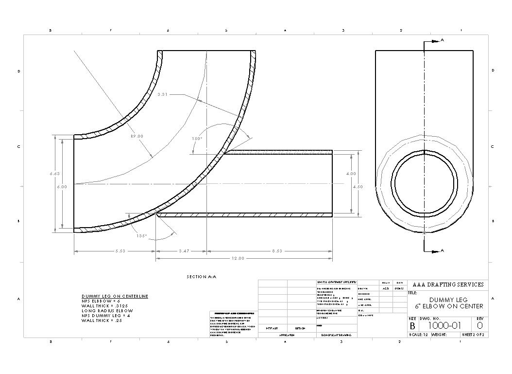
In the past, in order to figure out how to cut a stanchion or support pipe that intersected an elbow meant you to do parallel line development.
That meant hand drawing a section through the fitting where the stanchion intersected and then using your drafting machine to project horizontal and vertical guidelines onto a detail of the stanchion.
With a full size drawing made by parallel line development a welder/fitter can wrap the the drawing around the stanchion as a template and mark exactly where he or she has to torch cut or hand grind
Download a sample ![]() pdf full size drawing here
pdf full size drawing here
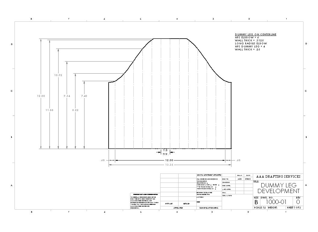
Needless to say the development template has to be dead nuts otherwise the stanchion wont fit and is just becomes scrap. (The welder fitter will have some choice words for you too !)
3d drafting software makes things a little easier because once you have the conditions modeled you can just dial in the necessary pipe diameters and cut the elbow through the stanchion to get the profile just right.
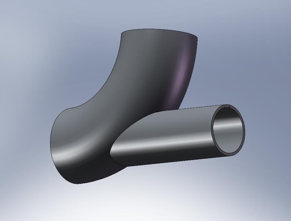
After that is done, you can generate the flat development using the CAD software. The only thing that needs to be done after that is to add guidelines on the drawing to aid the welder / fitter in locating the drawing once he or she uses it as a template.
This kind of template creation is not limited to the piping industry. It can be used with brackets for traffic signals for example, where one support tube has to join to a lamp post or support at an angle.
Do you need pipe templates ?
If you are joining pipes and need full size pipe developments printed out for pipe cutting, I can generate them and have the drawing couriered to you at the job site. I need some basic information about what you are joining
- The main pipe or fitting you are joining to and its size and specifications
- The size and specs for the branch pipe you need to cut
- The angle the branch pipe meets with the main pipe
- The offset if the branch pipe does not pass through the centerline of the main pipe
Pipe development drawings are printed full size so they can be wrapped around the branch pipe for marking and layout of the pipe.
Contact me at 905-467-0233 if you need more information
Scanning drawings and CAD conversion
Scanning drawings and large format scanner facts
Scanning drawings is worth considering if you have a lot of old legacy drawings. Pencil or ink drawings, sepias or blueprints, its often a good idea to get at least some of them scanned.
Scanning the drawings to tiff or pdf will preserve the images and allow the drawings to be used over and over again without worry about damage to the originals. Scanning also gives you the opportunity to add cataloging to your drawing files, so that its easier to find details and assemblies when you need them in a hurry.
Drawings are usually scanned to tiff format or pdf format or both. Tiff files have the advantage that they can be imported and overlaid on top of autocad drawings.
New geometry can be created without having to redraw old reference lines. So long as the old drawings are accurate and to scale, this process will work fine. The tiff files will have to accompany the cad drawing wherever it goes. Tiff files also dont offer any opportunity for catalogueing beyond their filename.
PDF files can be made from the Tiff files. PDF files are often smaller than the tiff files and so allow many drawings to be kept for reference purposes. It is also possible to perform OCR or optical character recognition on the tiff file prior to conversion into PDF format.
This has the advantage of allowing thousands of drawings to be searchable by name, drawing number, drawing title and even by notes within the drawing. That is so long as the OCR does not turn handwritten text into nonsense and goobledygook. You need to manually monitor this process to make sure it works, and edit the mistakes it makes. But when it works, OCR combined in a PDF file gives you powerful drawing searching capabilities.
There are some problems you can run into with scanning drawings. For one, any dirt or smudges will get transferred to the tiff file just like it was part of the drawing. Often you have to manually erase these artifacts later.
Handwritten text will often not be translated by OCR and have to be redone manually. Old blueprints wil have their blue background transferred to the tiff file. You will have to turn the image into a "negative" to get a white background with blue lines so that the tiff file is useable for CAD.
With old sepias, the tiff file will pick up all the old revisions made with erasing fluid. These messy areas will have to be manually edited later. All of this involves extra time and work, but depending on the importance of the old drawings, it may be worthwhile and quicker than redoing the whole drawing over in your CAD system.
Scan2Cad is a great software package if you want to do your own drawing scanning and raster to vector conversion. I have always liked their responsiveness to customer questions. You often get one of the software designers replying to your questions.
Scan2Cad works with your scanner to produce tiff files and many other formats. It also does raster to vector conversion which means it converts image (raster)files to CAD (vector) files. Scan2Cad converts hand drawn linework to linework that can be manipulated in your CAD system. This can be a huge timesaver.
For day to day scanning work, I have found that the Mustek 11" x 17" format scanner below is a good workhorse. It is not an expensive unit and if you need only a portion of a large drawing, larger "D" and "E" size sheets can be laid flat on its table since its top cover is easily removeable. This scanner can save you the cost of going to your local cad service bureau to get the odd scanning job done.
Geometric Dimensioning and Tolerancing
Geometric Dimensioning and Tolerancing - Thats something is something only engineers use ?
GDT&T attempts to pull together design, drafting, manufacturing and production so that they all work together toward a common goal - "Producing parts that fit together" first time and every time.
This goal is never more important now that the person who designs and drafts the part maybe thousands of miles away from the shop that ultimately makes the part. The maker of the part, may not even speak the same language as the designer making the drawing the only viable means of communicating how the part is supposed to be made.
Old fashioned coordinate toleranced drawings are simply not good enough in this sort of environment. While they may adequetely communicate the size and shape of the part, coordinate dimensions dont make it clear how the part is inspected. What are the most important dimensions.
Coordinate dimensioning and tolerancing may lead to parts being having faces machined unneccessarily and at extra cost. It may also result in ambiguous instructions for inspection where bad parts end up being accepted and good ones end up being rejected.
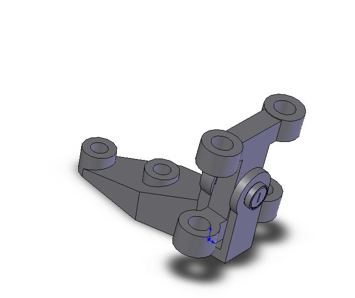
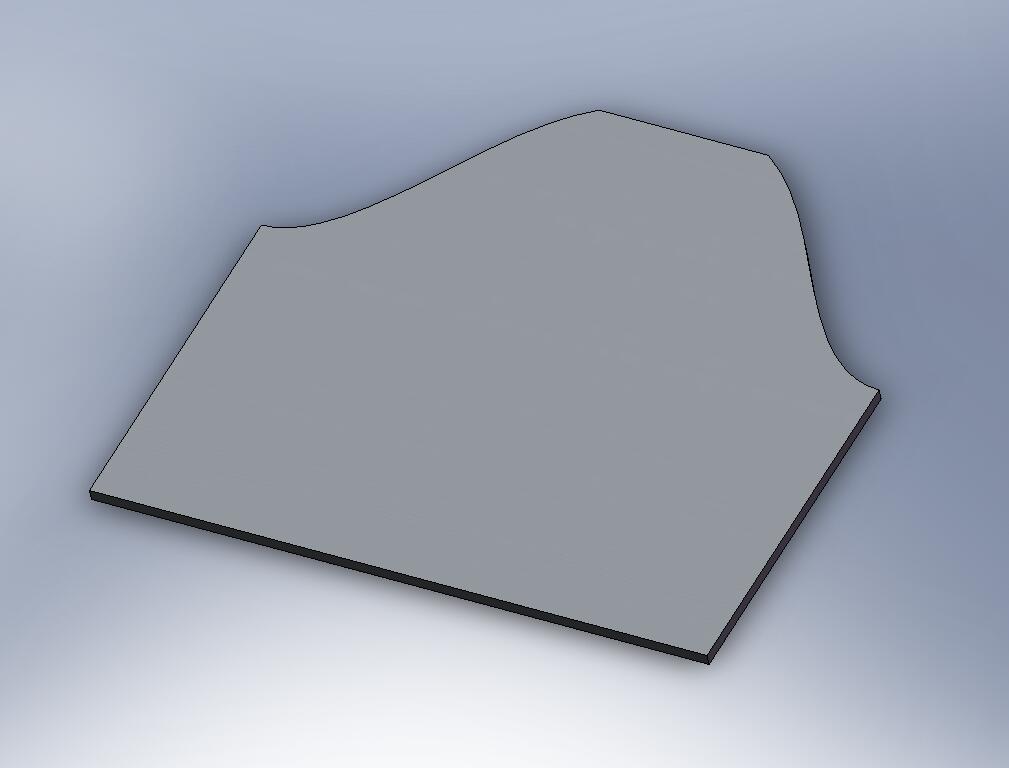
Perhaps the most important part of the GD&T dimensioning system is in ensuring parts go together by identifying the critical features. Take for example this railroad car disk brake assembly.

If we were going to be preparing the machining drawings for the base component for this disk brake, It is reasonably certain that the flat face on the base would be our primary datum. This is the face where the disk brake assembly attaches to the train.

Just by doing this we have not only identified the most important surface but also communicated to inspection that this ought to be the reference surface used to check the position and characteristics of all bolt holes, and machined features.
Using engineering scales
Most CAD systems allow the drafter to draw at whatever scale he or she feels like. However, if fabrication shops are going to be using your drawings you will help them far more by drawing views to commonly accepted engineering and architectural scales.
Many shops like to keep drawings to a consistent scale so fabricators get used to knowing how drawings are laid out. This is just as important in plant layout and architectural drawings where 1/8"=1'-0" and 1/4"=1'-0" are standards for construction and building permit work. In machine design 3"=1'-0" and 1-1/2"=1'-0" are very commonly used in weldments and small assemblies. Details often are full size or half size.
If estimators are going to be taking off material requirements from your drawings they will also need to have the drawings made to scale so they can calculate the number of panels required, steels sheets, rod or bar, whatever it might be.
Drawing to scale is also important since the CAD system can make scale templates more accurately than ever before. Drawings can be plotted at full scale and parts can be checked against them simply by placing them on the drawing. Paper plots can be glued to wooden forms and templates can be sawn to shape with minimal layout time.
The following table shows typical engineering scales and useful data to help set up your sheet layout.
| RATIO | DWG. SCALE | DECIMAL | RECIPROCAL |
| 1:1 | FULL | 1 | 1x |
| 1:2 | 6"=1'-0" | 0.5 | 2x |
| 1:4 | 3"=1'-0" | 0.25 | 4x |
| 1:8 | 1-1/2"=1'-0" | 0.125 | 8x |
| 1:16 | 3/4"=1'-0" | 0.0625 | 16x |
| 1:24 | 1/2"=1'-0" | 0.0417 | 24x |
| 1:32 | 3/8"=1'-0" | 0.03125 | 32x |
| 1:48 | 1/4"=1'-0" | 0.0208 | 48x |
| 1:64 | 3/16"=1'-0" | 0.0156 | 64x |
| 1:96 | 1/8"=1'-0" | 0.0104 | 96x |
| 1:128 | 3/32"=1'-0" | 0.0078 | 128x |
There is also a small engineering scales power point presentation with sound that I put together about this subject. It's worth a listen if you are just learning the process of setting up drawings to scale.
 You can use this chart in many different ways. Most often you would be starting off with an autocad file that was drawn full size in model space and now needs to have a drawing border to a specific drawing scale placed around it.
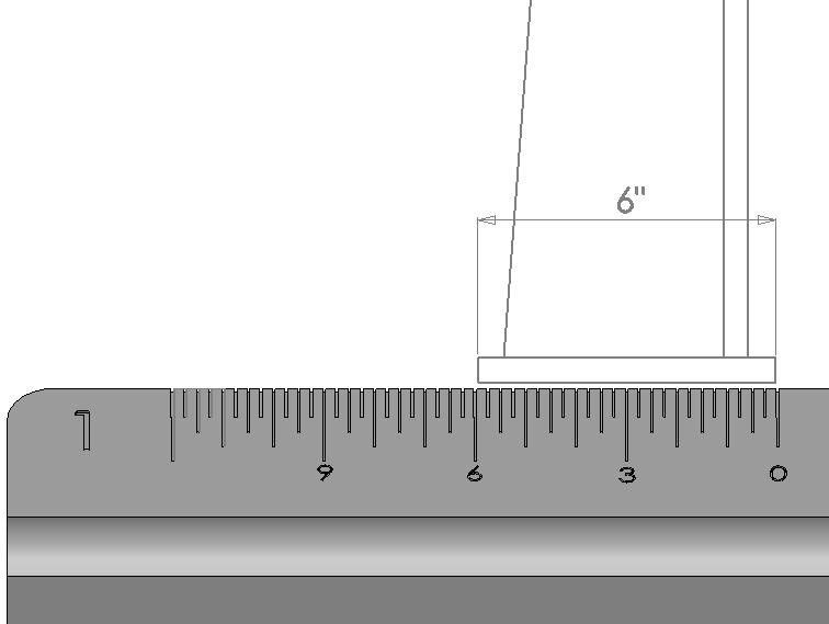
How to Scale a drawing to make sure it is accurate
- Back in the day you could only buy scales individually, not all in one kit like this one from Amazon. Plus they are made from more durable aluminum not plastic. 3 12 inch scales with 3 sides each cover 1-1/2" = 1'-0", 1" = 1'-0", 3/4" = 1'-0", 3/8" = 1'-0", 3/16" = 1'-0", 3/32" = 1'-0", 1/2" = 1'-0", 1/4", 1/8" = 1'-0" and 3 = 1'-0"
 |
|
 |
|
Simply draw your drawing border actual size and scale it up using the reciprocal numbers until your object fits nicely within the drawing border. Under drawing scale in the title block, label the scale from the chart whose reciprocal created the best fitting border
Also if you have a drawing border that is 3/4"=1'-0" and you want to make it 1/2"=1'-0" look up the reciprocals for both scales. Since you are making your drawing border smaller in this case you need to divide 16/24 = .6666667. Scale the original border down by this amount and your scale is changed.
The Ratio and Decimal numbers can be helpful if you are working in paper space and need to know what the scale factors are for window resizing in order to create the proper scale.
Calculated Industires has this neat little gadget for scaling off large printed drawings. This is particularly useful for estimators who must quickly find linear feet of cladding or pipe or any number of items from a large drawing set. The device works by first setting the scale then rolling a small wheel along the length you want to measure and reading the distance.
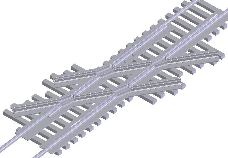
Diamond Crossing
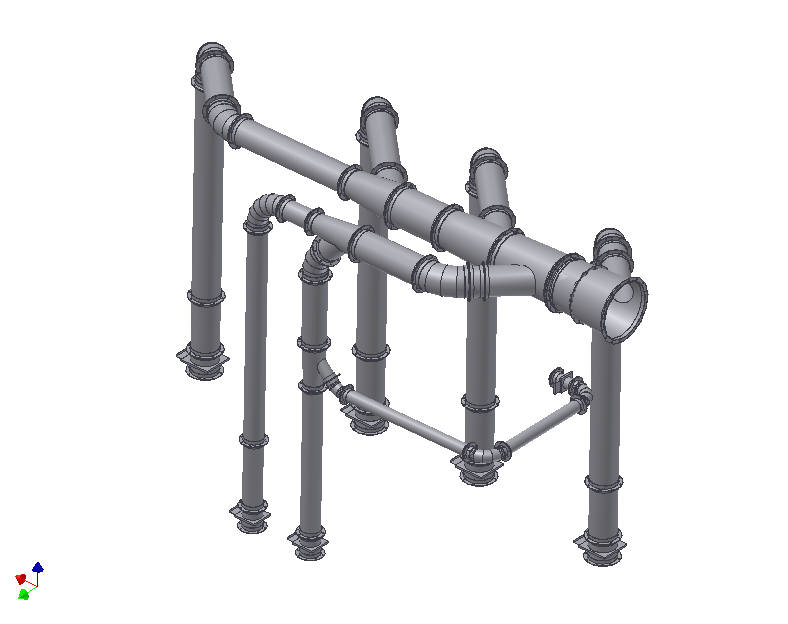
Duct Layout