Wastewater Clarifier
In the past, trigonometry and a custom developed formula was used to size the squeegee blades and their mounting brackets. But with hand drawn drawings and even 2D CAD drawings, it was difficult to be sure that they were working with an optimum solution. Using a 3D model offered many advantages, the main advantage being that once a good model was was developed, it could be used over and over again to develop new wastewater clarifiers.
Setting Up the Model
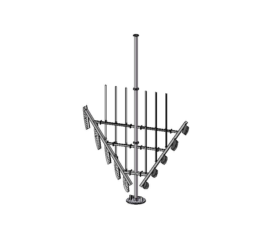
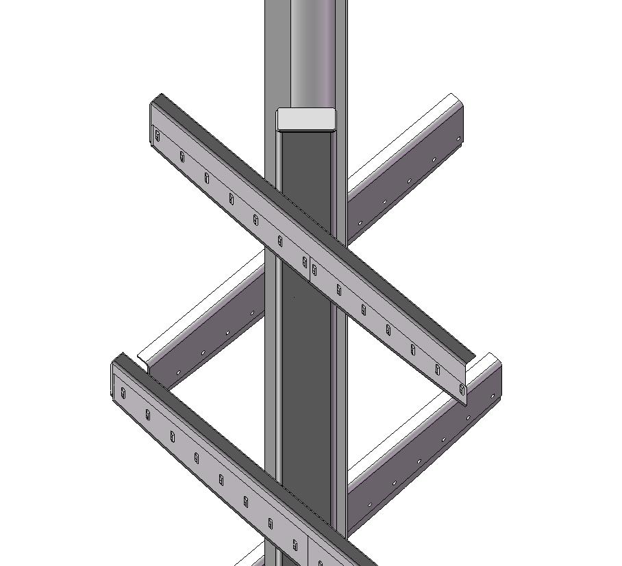
This clarifier was modelled according to the customers typical bill of material structure. The model was broken down into a series of weldments with fasteners to hold them all together. There was the 3 shaft sections, which were 3 configurations of a single weldment file. The Rake Arm weldments and weldment files for the pickets and braces that supported the rake arms.
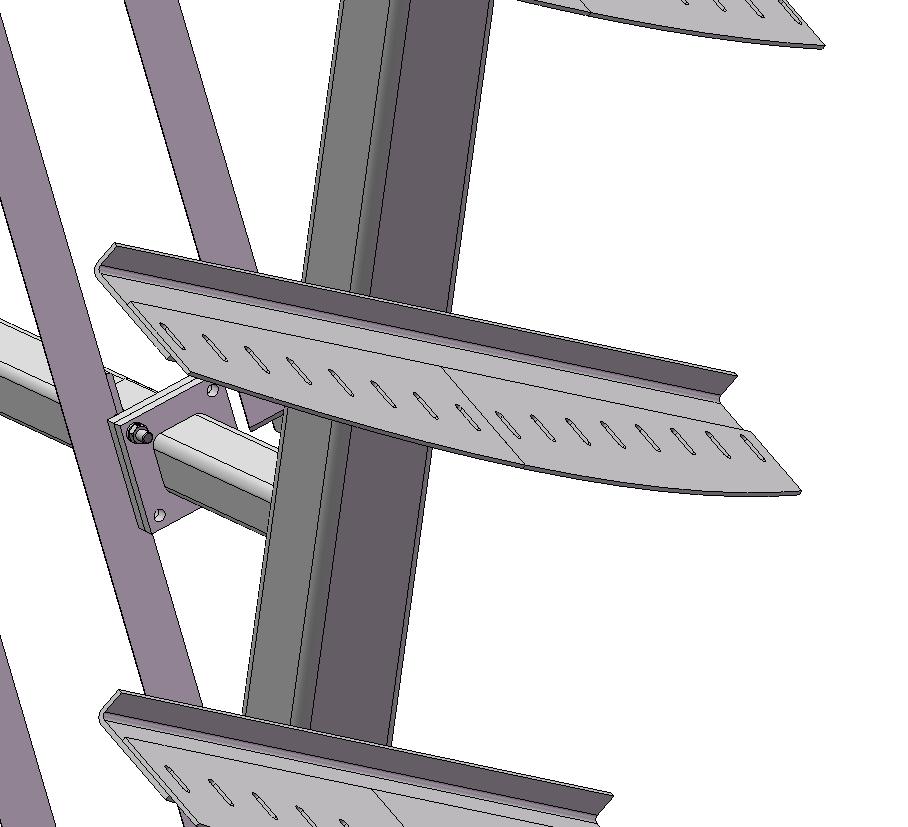
The all important squeegee blades and their supports were modelled as a weldment file also. Keeping all the blades in one file made it easier to modify them to conform to the shape of the vessel. Making the blades as a soldiworks weldment was also useful since 1 blade could be patterned the resulting pattern of blades could be individually cut and modified to suit the needs of the shape of the vessel. 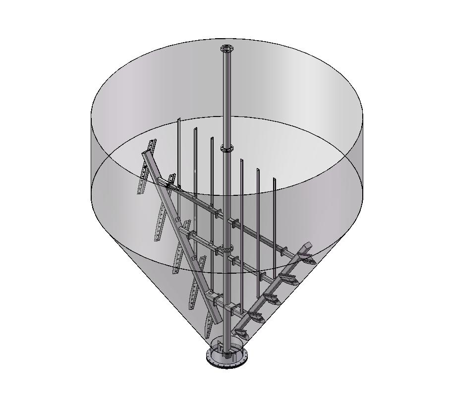
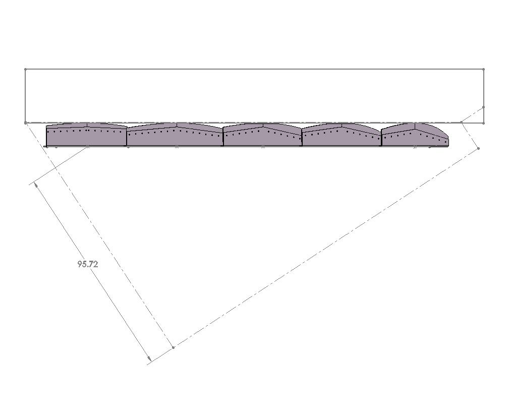
 To model the blades it was only necessary to lay out a sketch with a single line representing the bottom of the rake arm where the blades were to be mounted. Then another single line at 45 degrees to the rake arm represented the first squeegee at the top of the rake arm. This line was extruded and became the first squeegee bracket. A line was then sketched on the bracket and this was in turn extruded into the squeegee blade itself. The blade and the bracket were initially simply made rectangular in shape. The blade and brackets could then easily be patterned down the length of the rake arm in whatever quantity was required.
Using the Clarifier Vessel to cut the blades
The neat thing about using multi body parts like weldment files is that you can make many irregular shaped parts sometimes with one single operation. This was the case with the clarifier. With the squeegee blades and their brackets patterned all that was necessary was to accurately model the profile of the vessel. The model of the vessel had 1/2" clearance built in as the distance between the squeegee blade and the vessel wall itself. The vessel sketch could then be used for a rotated cut right through all the patterned squeegee blades using the centerline of the driveshaft as the axis for the cut. The result was a complete set of different squeegee blades all cut to conform to the shape of the vessel
 If the cut resulted in any interferences it was easy enough to adjust the patterning of the blades as well as the width and postion of the squeegees. This allowed the creation of a set of blades that were easy to fabricate and install in the field. The adjustability built into the model also allows the creation of a wide range of similiar size clarifiers to be built according to client requirements. This practice makes sure that previously designed components get reused over and over again, which keeps design costs in check
Wastewater equipment design is one area where 3D modelling can really help solve some tough problems and control costs at the same time.